Today’s topic is Electrical Symbols On Architectural Drawings. Obviously, you can find a great deal of Industrial Electrical Symbols Pdf-related content online. The proliferation of online platforms has streamlined our access to information.
There is a connection between the A complete guide to electrical drawings, blueprints & electrical wiring. and Electrical Drawing For Building Pdf information. more searching has to be done for Construction Drawing, which will also be related to Electrical Symbols Socket.

46 Things About Electrical Symbols On Architectural Drawings | Iec Symbols For Electrical Drawings Pdf
- Recall that every drawing has its symbols with descriptions that are provided in the legends. Electrical systems such as lights, switches, circuit breakers, distribution panels, and fixtures are denoted using various symbols described in legends. An electric planer is an instrument that helps to shave and shape wood. - Source: Internet
- Electrical symbols often feature a subscript — small writing at the bottom of the symbol — that helps explain the outlet’s function or rating. If you see a symbol with a subscript, it should be explained somewhere in the blueprint’s legend. (For more information on abbreviations, see the section below.) - Source: Internet
- Next, an RCP contains symbols that show the height and other dimensions of the roof. So basically, you can find out everything you need to know about a ceiling simply by looking at this plan. It also shows the alignment and layout, and occasionally some ornamentation too. - Source: Internet
- Floor plan symbols are basically looking down from the top of the house. In-floor plans we found this type of symbols, it includes furniture, windows, doors, etc. Some common symbols of floor plans are compass, doors, stairs, windows, walls, applications. - Source: Internet
- The legend defines architectural symbols and notations on the plan. Many standard symbols appear there for specific projects. However, there can be variations in how symbols look and what they represent, which makes consulting the legend essential for each project. - Source: Internet
- The electrical drawings include lighting fixtures and appliances that are provided in symbols on the plans. All the equipment needs to be described to estimate, order, and install at the site. The schedules fulfill these requirements. - Source: Internet
- The electrical drawings consist of electrical outlets, fixtures, switches, lighting, fans, and appliances. General notes, abbreviations, legends, and symbols, are found on the first page of the electrical drawings. Schedules help to find the details of the equipment or fixtures used on the plans. - Source: Internet
- Also, the same material might be represented using one symbol in section and another in elevation, so that can be a little tricky. It might give you an idea that those materials are different when in reality, it’s the same one. Want to know why these symbols differ? - Source: Internet
- In floor plans depicting kitchens, bathrooms, and laundry rooms, you’ll see symbols for appliances like the refrigerator, stove, washer, and dryer. These usually appear near plumbing elements like sinks, showers, toilets, and drains. Symbols can be accompanied by labels or abbreviations that further explain their functions, or not. - Source: Internet
- Blueprints are basically the combination of some symbols. Blueprints symbols are used to indicate objects, functions or systems in the plan of engineering drawing. Blueprints symbols are generally used in architectural drawing, structural drawing, electrical drawing, etc. - Source: Internet
- The material symbols are a sub-category of architecture-related symbols and display the material or the content of the drawings, floor plans, or elevations. At times, different symbols can be used to depict the same material. Hence, stay clear of assuming anything and pay close attention to the symbol legend while interpreting any drawing. - Source: Internet
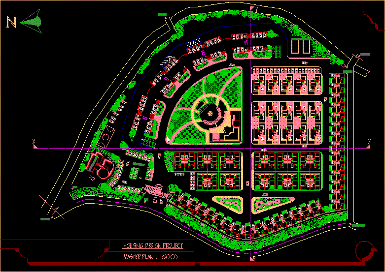
- Architectural technical drawings primarily include plan and section drawings. The symbols used in drawing floor plans, master plans and site plans are almost the same for each country. The symbols you’ll see in the example below are symbols used to show levels on plans. You can show the elevation levels on the plans by choosing any of these symbols. - Source: Internet
- Scales vary in complexity, from the simple (1 inch = 1 foot) to the complex (3/16 inch = 1 foot). Plans are often drawn at 3/4, 3/16, 1/8, and other scales (in each case the dimension in inches here corresponds to one foot). The symbols are also drawn to scale so you will get an accurate idea of how elements of a room are configured in the space. - Source: Internet
- For reference, every set of architectural drawings includes a symbol legend. If you aren’t familiar with a symbol, you will be able to find it in the legend. Floor plan notes give additional context for the building. For instance, the notes can clarify exactly to what point on a wall dimensions should be measured. - Source: Internet
- For example, construction companies may use their own unique blueprint symbols in their set of drawings. Also, several different-looking symbols may represent the same item, depending on who you ask. Or one symbol may mean different things to workers with different specialties. Always search the legend on each unique plan to be clear about what the symbols mean. - Source: Internet
- Electrical plans are generally drawn at the same scale as the floor plans. The scale provided on the plan helps to measure the size, length, and distance of the equipment. The most common scale is 1⁄4" = 1’-0" (1:50 metric) for residential and small commercial projects, and 1⁄8" = 1’-0" (1:100 metric) for large commercial ones, where electric symbols work. - Source: Internet
- Component symbols are those accessory symbols that don’t play a crucial role in the structure of a property and are just used for reference purposes. These include illustrations of fixtures like sink, bathtub, toilet, etc., and furniture pieces. - Source: Internet
- On a simple scale, one inch represents one foot, or another simple whole number, whereas the complex ones follow fractional proportions. A scale on which 3/16 inches represent one foot is considered to be fairly complex. 3/16, 3/4, 1/8 are other scales that are commonly used in construction drawings. - Source: Internet
- A derivative of the landing scheme. This diagram shows the lines and symbols in a simple way, often from one or more light and power divider units. In addition, specific technical features of each group are often displayed, such as power output and nominal current. Also, for each distributor, the total expected ability is specified. - Source: Internet
- Piping drawings are made using plumbing symbols to simplify the construction for everyone and save some time along the way. All the fixtures, pipe-fittings, valves, and several other components are showcased using plumbing symbols. To give you a better picture, we’ll tell you about a few of these graphic symbols, so stay with us and keep reading. - Source: Internet
- Apartment blueprints often include component symbols like microwaves, coffee tables, ACs, etc., to give the potential customers an idea of the area. It’s also a good demonstration of how to design and arrange furniture in specific rooms. - Source: Internet
- Each of the components of the architectural plan will have its own set of symbols and notes. Architects and designers work with the floor plans, and you’ll also see exterior and interior elevations, and reflected ceiling plan (RCP). Here are the most common found on each type of print . - Source: Internet
- We already talked a little about doors in the previous section, but we’ll elaborate a little more as they are an integral part of every floor plan. The symbols used for doors have two components: two parallel straight lines depicting the width of the door and the curved part that shows its range of motion. The curvature mainly shows the direction in which the door swings open and gives a rough idea of the clearance area. - Source: Internet
- A floor plan is one of the construction drawings that you’ll find included in a set of blueprints. They appear alongside site plans, elevation plans, and other detailed working drawings that offer builders a road map for how to build a structure. They serve as the fundamental kind of house plan for general contractors and others working in the construction industry. - Source: Internet
- The commercial buildings consist of multiple similar areas like apartments and hotel rooms. The multiple area floor plans are represented on drawings by a code or reference name on the floor plan. In electrical plans all the wiring layout are found in these plans. - Source: Internet
- Electrical blueprint symbols are very important symbols in engineering drawing. Electrical symbols are included to omit the excess delay of an electric circuit. Electrical blueprint symbols are used in engineering drawing to understand easily for workers and drafters. - Source: Internet
- Accelerate your electrical schematic designs with this complete library of IEC and ANSI standard DWG symbols. Get the full library (a $200 value) for a limited time only at no cost to you. Take advantage of the complete SOLIDWORKS® Electrical symbol libraries. These libraries contain industry standard symbols for every industry allowing for quick schematic creation for electrical design professionals. - Source: Internet
- Recall that the schedules include manufacture, type, model, size, and details of the equipment. The electrical drawings include schedules for the light fixture, equipment, and load details, as shown in the image. Schedules help to know details of the equipment or item used on the electrical plans. - Source: Internet
- Mainly two types of symbols can be seen in these systems, the main lines, and the subordinate branching lines. The main ducts are drawn with heavy line weight or a rectangle depicting its actual shape, while the branches are represented by single lines. The dimensions are mentioned adjacent to these lines to make it easier for you to visualize the space taken up by these elements. - Source: Internet
- The full form of HVAC is heating, ventilation and air conditioning; these symbols are compacted in one place. These symbols are generally denoted vents of AC, outside part of the building, etc. HVAC symbols are containing some symbols like wall vents, furnaces, ceiling vents, etc. - Source: Internet
- Floor plans use stylized symbols that often look like the outlines of elements they represent. Tubs, stoves, sinks, and stairs are familiar examples. These can appear along with built-in elements of interior design, like appliances, islands, cabinets, and bookshelves. - Source: Internet
- These professional blueprints display the exact locations of various fixtures and routes of the connection lines. As a framer, you’re expected to know where the MEP systems are routed in a property so you can plan out the interior accordingly, leaving spaces for the outlets. This is the primary function of MEP drawings. - Source: Internet
- In order to fit all the information about a layer of a building onto a page, construction drawings and architectural drawings are drawn so that a small increment of measurement represents a larger increment. This means that the plans are drawn “to scale.” Every symbol on the legend is drawn to the same scale as the rest of the floor plan. - Source: Internet
- A drawing showing the exact location of electrical devices (such as switches, WCDs, data / telephony terminals) on an architectural map. Installation drawings can be subdivided into installation drawings for power groups (400 / 230Vac), light groups (230Vac), electrical engine compartments, grounding, communications and fire prevention. You can also combine these types of items into one (or more) drawing (s). - Source: Internet
- There are different symbols for different types of doors, depending on their hinges, direction of opening, number of doors, mechanism of opening and closing, etc. And the same goes for different types of windows. Double-hung, single-hung, right sash over left, left sash over right, etc., are a few common types, and each one has its own unique sign. - Source: Internet
- Section drawings provide more information on how a building, interior space, or equipment is installed. It may be divided into one or more multiple views through the assembly in a vertical direction. Section drawings take such an imaginary slice through an object or building. - Source: Internet
- Other types of prints within the architectural plan include MEP, or Mechanical, Electrical, and Plumbing. They are usually delivered in a bundle on a separate drawing with the relevant mechanical, plumbing symbols, and electrical symbols. As a builder or framer, you’ll need to know where those systems will be routed so you can leave space for them to be laid in. The MEP drawings will show the location of physical fixtures and the routing of the lines. - Source: Internet
- Walls are generally two types; interior walls and exterior walls. Both walls are drawn by two parallel lines but exterior wall lines are dark, thick and interior wall lines are light. Appliances: These are basically the other symbols in floor plan which are bathtub, toilet, sinks, other furniture, etc. All appliances symbols are drawn by single lines. - Source: Internet
- Legends contain abbreviations with symbols used for appliances, switches, panels, and other fixtures shown in a plan view. Floor plans do not include notes or details for all those symbols used on the plan. The best practice is to refer to legends before moving on to the plans. - Source: Internet
- A scheme showing the lines with the number of veins and symbols in a single way. Such a scheme often shows (a part) of the configuration of an electrical installation. The function of a landscaping and a block diagram are often in line with each other. - Source: Internet
- The switch symbols are drawn perpendicularly to the wall and are read from right to left or from the bottom. The electrical construction drawing for a small land or property usually includes wiring and small devices like receptacles, appliances, light fixtures, and switches. It is basically a blueprint that indicates which light is connected to which controller. - Source: Internet
- It’s because the symbols draw inspiration from real life, and as you must have observed, several construction materials look different when seen from different directions. Architects and engineers take that view into account and set the symbols accordingly. For instance, a concrete block is drawn a certain way in elevated areas and some other way in sections. - Source: Internet
- Electrical drawings should only be prepared by competent drafters with electrical expertise to avoid unnecessary errors and delays. Electrical symbols are used to simplify the work for both the planners and the engineers interpreting the drawings. However, these signs and symbols aren’t uniform all across the industry, and that’s why a drawing involving electrical symbols usually contains symbol legend. - Source: Internet
- In the example below, you can see the symbols used in the roof, window sections and the view. Level symbols used in the plan are also in the same drawing language in the views and sections. For architects and engineers studying technical drawings, it is very important to prepare clear and understandable drawings. For this reason, the symbols you use should be simple and understandable, and consistent in terms of cross-sections and plans. - Source: Internet
- Next are the symbols used for electrical projects. These signs are used all over the world to symbolize all electrical elements and electronic connections included in the architectural project. You have to use these symbols to represent every element in your plan drawings, from electrical sockets to TV connections to electrical panels. Since you, as an architect, have covered every detail, or rather every point, of your projects, the best way to convey these details is to use symbols. With electrical drawing symbols, you can show the types of electrical socket in the room and location of electrical panels or any detector that you have decided. - Source: Internet
- Architects and builders draw reflected ceiling plans (RCP) to show the dimensions, materials, and other key information about the ceiling of each of the rooms represented on the blueprint. It takes its name from the idea that you are looking down at the ceiling as though there were a mirror on the floor reflecting the ceiling’s plan back to you. Here are common RCP symbols: - Source: Internet
 Following are some suggestions on where to begin your search for data on HiSoUR – Hi So You Are:
You should try to find Industrial Electrical Symbols Pdf-related information from reputable places. Libraries, online resources, and even paid journalists all fall under this category.
Following are some suggestions on where to begin your search for data on HiSoUR – Hi So You Are:
You should try to find Industrial Electrical Symbols Pdf-related information from reputable places. Libraries, online resources, and even paid journalists all fall under this category.It’s crucial to be aware of the many electronic media sources available when researching Electrical Symbols For Drawings Pdf, such as Google and YouTube. You may also get info about Electrical Symbols Socket on social media sites like Facebook and Twitter.
Video | Electrical Symbols On Architectural Drawings
It’s crucial to read to examine the authenticity of each source in order to acquire the greatest information regarding Electrical Symbols Used In Electrical Layout/Plan Of The Building. You’ll learn more about Cad Blocks Electrical Symbols after watching the films included in this post, which come from a variety of different sources. Information on a wide range of topics may be easily accessed via the internet.
## Notable features of Electrical Drawing Symbols For House include:- Electrical Symbols On Architectural Drawings
- Electrical Symbols On Architectural Drawings Uk
- Electrical Symbols In Architectural Drawing
- Electrical Symbols On Construction Drawings
- Electrical Symbols Architectural Plans Uk

Because there are so many websites and forums that provide information about Section Drawing, it should not be difficult for you to locate the data that you want.
The majority of individuals are accustomed to taking a completely different approach when it comes to obtaining information regarding Architectural Blueprint Symbols. This makes it possible to take a more in-depth look at the information that is available about Electrical Drawing Symbols For House and how it might be utilized.

methods for producing information displays about Section Drawing that are both aesthetically pleasing and functional. In commercial and marketing settings, as well as for the purpose of conveying information on Residential Electrical Symbols Pdf, they are useful tools to have. Because of this, we also supply some photographs relating to electrical symbols architectural plans uk.
In summing up, I’d like to say that this article offers a general summary of Electrical Symbols For Drawings Pdf. Also covered are HiSoUR – Hi So You Are and Industrial Electrical Symbols Pdf, which serve as a benchmark for evaluating the depth of your understanding of What Is Blueprints Symbols | Construction Blueprint Symbols | Electrical Blueprint Symbols | Floor Plan Blueprint Symbols.