Today’s topic is How To Test Amperage With A Digital Multimeter. Obviously, you can find a great deal of how to measure amperage with a digital multimeter-related content online. The proliferation of online platforms has streamlined our access to information.
There is a connection between the How To Use Multimeter and Measure Current With Oscilloscope information. additional searching needs to be done for Multimeter Basics, which will also be related to Digital Multimeters (DMM).
97 Things You Should Know About How To Test Amperage With A Digital Multimeter | How To Use A Multimeter For Beginners
- Multimeters are great electrical devices that are used to measure electrical currents. Professionals can use multimeters to check voltage, resistance, and electrical current levels by connecting two leads to various electrical system components. This device is also sometimes referred to as a volt-ohm meter or volt-ohm-milliampere (VOM). - Source: Internet
- It’s important to check the manual of your multimeter to see where it draws the line in terms of “low resistance” to sound the continuity buzz. This resistance is around 20-ohms for many multimeters. To test for continuity using a benchtop multimeter, set the multimeter to continuity mode by pressing the button that looks like it has a sound symbol. Connect the positive probe to the “INPUT HI” port, the negative probe to the “INPUT LO” port, and ensure the circuit or device under test is powered off. Probe various points on the circuit and listen for the continuity “beep”. - Source: Internet
- Do you have a multimeter but are confused about how to use it or are getting unexpected readings? If so, the sections below will help you sort through what to do. If there are words or concepts you do not understand, or symbols on your multimeter that puzzle you, return to the Multimeter Overview tab. If you are looking for multimeter usage ideas or labeled photographs of assorted multimeter models, then visit the other tabs in this multimeter tutorial. - Source: Internet
- Turn the power back on once you have safely connected your multimeter in series. Do not touch any live wires or you can be fatally injured. Hold your probes as far from the metal tips as possible while maintaining control. - Source: Internet
- This includes time and frequency measurement applications, i.e. time measurement and fast frequency. A digital multimeter can also be useful when measuring resistance, including measuring resistance with a constant current, measuring resistance with a constant voltage, and a micro ohmmeter. Current measurements may be another reason why a multimeter is needed, such as true RMS AC and DC measurements. - Source: Internet
- When you are looking for the best digital multimeter for your needs, the obvious place to begin is by figuring out what you need this tool for. As a digital multimeter is a very versatile testing tool, it can be used for many different things. Therefore, you need to think about whether you are looking for such a tool for full-time professional use or whether you are only going to be using this on occasion. This will help you to determine whether or not you need extremely high levels of reliability and accuracy. When it comes to purchasing a digital multimeter for professional use, these are qualities that you simply will not be able to compromise on. - Source: Internet
- Knowing how to test a battery using a multimeter is important to ensure the battery is working at optimal levels and is not showing symptoms of wearing out. A battery failure can lead to seemingly increasing problems in the hardware of an electronic system or starting troubles in a car. A multimeter can be used to check the voltage and current produced by a cell which helps to recognize a faulty battery that may be replaced. The symptoms of a poor battery and how to test a battery with a multimeter are discussed below. - Source: Internet
- As touched upon, you do have a varied selection of digital multimeters to select from today, and so looking at the features is important. All of the multimeters on the market will have current and voltage meters. Plus, most of them will be able to measure resistance. However, a lot of the products will go further than this and they will have a number of added features depending on the price tag and the manufacturer. This includes the likes of frequency, capacitance, and continuity, and so you should assess what sort of features you will receive. - Source: Internet
- Some multimeters have a continuity check, resulting in a loud beep if two things are electrically connected. This is helpful if, for instance, you are building a circuit and connecting wires or soldering; the beep indicates everything is connected and nothing has come loose. You can also use it to make sure two things are not connected, to help prevent short circuits. - Source: Internet
- With a digital multimeter, it will combine the testing capacity of a single-task meter - ohmmeter (ohms), ammeter (amps), and voltmeter (for measuring volts). Usually, they will incorporate a number of advanced options or added specialized features. This means that technicians with more specific needs are able to find targeted models that are better suited for their needs. - Source: Internet
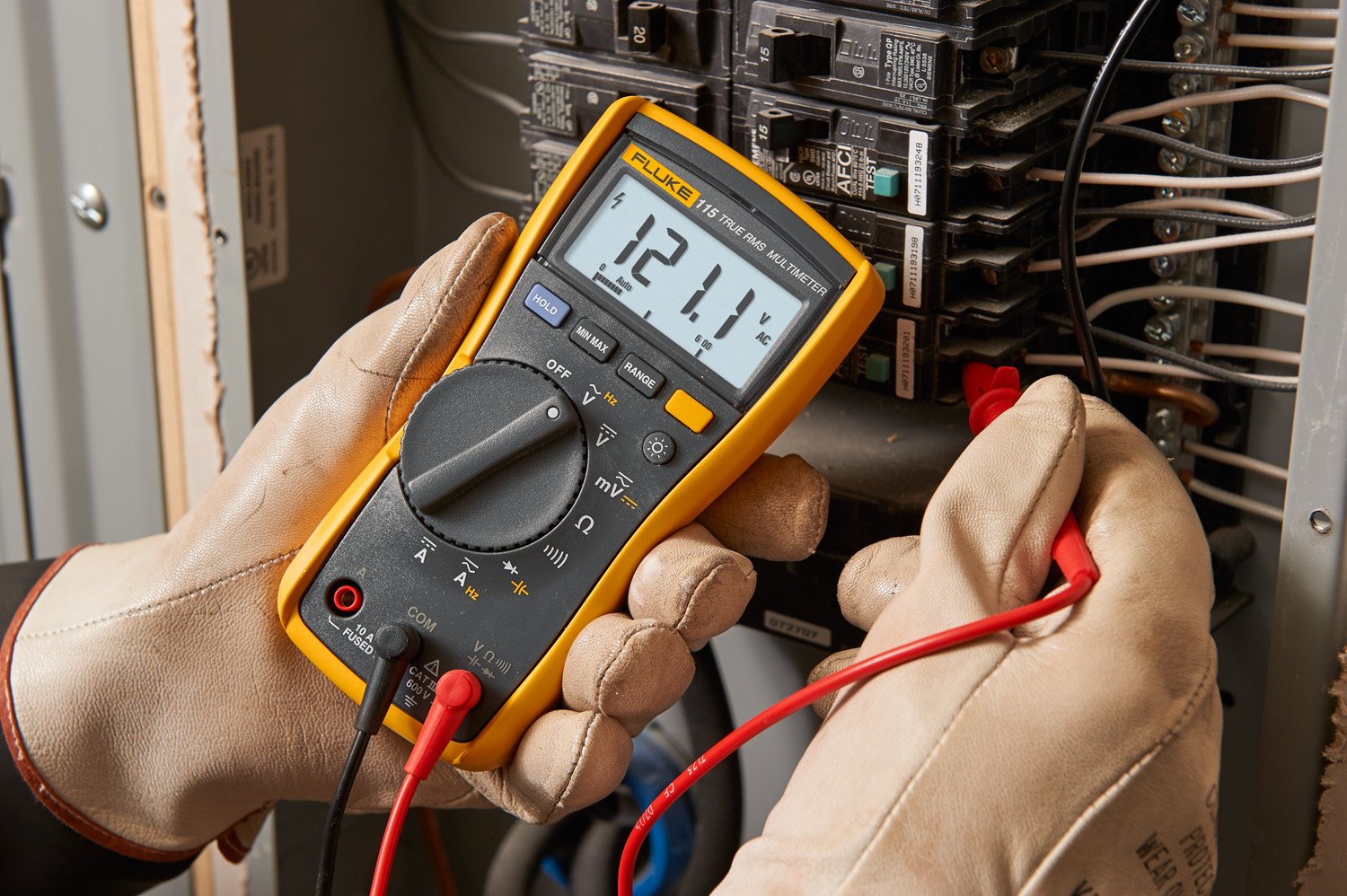
- The current should be reading on your multimeter display. The units will be shown on the multimeter display as well. In the example to the right, your meter is reading 0.79A of AC current. - Source: Internet
- Advanced multimeters might have other functions, such as the ability to measure and identify other electrical components, like transistors or capacitors. Since not all multimeters have these features, we will not cover them in this tutorial. You can read your multimeter’s manual if you need to use these features. - Source: Internet
- An electronic device called a multimeter is used to test circuit resistance, amps, and voltage. Professionals can use multimeters to check voltage, resistance, and electrical current levels by connecting two leads to various electrical system components. This device is also sometimes referred to as a volt-ohm meter or volt-ohm-milliampere (VOM). - Source: Internet
- To measure the current through a lightbulb the multimeter becomes part of the circuit and transfers electricity from the battery to the lightbulb. The positive probe of the multimeter (red) is connected to the positive side of a battery while the negative probe of the multimeter (black) is connected to one lead of a lightbulb. The free lightbulb lead is then connected to the negative side of the battery using wire. Current will flow from the battery to the multimeter and then into the lightbulb. - Source: Internet
- You will probably need to open up your multimeter to access the fuses (Important: Always disconnect the probes before you do this). Some multimeters have covers that will pop or slide off, and some have screws that must be removed first. Fuses usually look like small, glass cylinders with metal caps on the end and a thin wire running down the middle: - Source: Internet
- Most multimeters also use metric prefixes. Metric prefixes work the same way with units of electricity as they do with other units you might be more familiar with, like distance and mass. For example, you probably know that a meter is a unit of distance, a kilometer is one thousand meters, and a millimeter is one thousandth of a meter. The same applies to milligrams, grams, and kilograms for mass. Here are the common metric prefixes you will find on most multimeters (for a complete list, see the References tab): - Source: Internet
- Modern digital multimeters are capable of measuring incredibly minute variations or fluctuations. Although some multimeters test wider voltage ranges, experts point out that it will be harder to spot tiny changes in these higher ranges. The analog multimeters use a microammeter with a moving pointer to display readings. - Source: Internet
- A measurement device that can assess several electrical characteristics is a multimeter. The term “volt-ohm-milliammeter” (VOM) refers to a multimeter that has the ability to measure voltage, resistance, and current. This is because the device has a voltmeter, ammeter, and ohmmeter functions. Some include the measuring of other characteristics like capacitance and temperature. - Source: Internet
- If your multimeter is not auto-ranging, you might need to adjust the range. If your multimeter’s screen just reads “0,” then the range you have selected is probably too high. If the screen reads “OVER,” “OL,” or “1” (these are different ways of saying “overload”), then the range you have selected is too low. If this happens, adjust your range up or down as necessary. Remember that you might need to consult your multimeter’s manual for specifics about your model. - Source: Internet
- Although they come with two probes, many multimeters have more than two places in which to plug the probes, which can cause some confusion. Exactly where you plug the probes in will depend on what you want to measure (voltage, current, resistance, continuity test, or diode test) and the type of multimeter you have. We have provided one example in the images below—and you can check our gallery for a multimeter similar to yours—but since all multimeters are slightly different, you might need to consult the manual for your multimeter. - Source: Internet
- When we talk about a multimeter, we are talking about a universally applicable measuring device for various electrical quantities. By the way, this is where the name comes from: “Multi” simply stands for the fact that different measurements can be performed. Not least because of this, it can also be used in diverse applications ranging from hobbyist use in a wall socket to resistance determination of circuits in a professional environment. - Source: Internet
- Deciding on the best multimeter can be a daunting task. The price ranges can vary widely by brand and features. Be sure to explore all considerations that must be factored in when choosing a benchtop multimeter. - Source: Internet
- One of the most crucial tools in an electrician’s toolbox is digital multimeters (DMMs). They provide a wide range of functions and make it quick and easy to figure out what’s happening with your electrical system. But more significantly, they provide a trustworthy way to identify the lack of voltage. - Source: Internet
- In order to check the fuse, connect the multimeter in resistance mode by turning the selector knob. Place the probes in the “COM” and “mAVΩ” socket if your meter has the same socket for voltage, resistance and low current measurement. If your meter has a dedicated socket for low current measurement then place the black probe in VΩ socket and the red probe in the mA socket. - Source: Internet
- The same value might appear differently when measured with a different scale selected on the multimeter dial. For an example, let’s use measuring the DC voltage from a AA battery—which we expect to be 1.5V—using a multimeter that has settings for 200mV, 2V, 20V, 200V, and 600V. When measuring the battery with each setting, we get these readings: - Source: Internet
- Depending on the model, a multimeter can read a wide range of values. Basic testers can be used to check continuity, a quick test to confirm a full circuit, and they measure voltage, amperage, and resistance. Advanced multimeters can check for AC (alternating current) voltage and amperage, DC (direct current) voltage and amperage, resistance (ohms), Capacity (farads), Conductance (siemens), Decibels, Duty cycle, Frequency (Hz), Inductance (henrys), and temperature Celsius or Fahrenheit. - Source: Internet
- Direct current DC is unidirectional current, unlike AC. Therefore, its direction and polarity matter. If the probes are connected with opposite polarity, it will not damage a digital multimeter but only show a negative “-” sign. But if an analog multimeter is used, the reverse current may damage the meter because the needle cannot deflect in opposite direction and if the voltage is high it may damage it. - Source: Internet
- A multimeter is a handy tool that you use to measure electricity, just like you would use a ruler to measure distance, a stopwatch to measure time, or a scale to measure weight. The neat thing about a multimeter is that unlike a ruler, watch, or scale, it can measure different things — kind of like a multi-tool. Most multimeters have a knob on the front that lets you select what you want to measure. Below is a picture of a typical multimeter. There are many different multimeter models; visit the multimeter gallery for labeled pictures of additional models. - Source: Internet
- In addition to considering the specifications regarding the multimeter, it is also a wise idea to carry out your due diligence and do a little bit of digging online so that you can find out what the general feedback is regarding the device in question. After all, you will want to make sure that the product lives up to the sales pitch and that it is easy to use and performs as well as it should. Reading reviews and comments that have been left by previous purchases is the best way to get an honest assessment regarding the multimeter in question. - Source: Internet
- Disconnect the wire leading into the component you are measuring. There should be an open gap in the circuit now. Press one multimeter lead to the end of the disconnected wire. The other lead should be pressed into where the wire would connect into the component. - Source: Internet
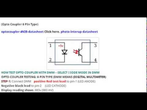
- Some multimeters also have a diode check function. A diode is like a one-way valve that only lets electricity flow in one direction. The exact function of the diode check can vary from multimeter to multimeter. If you’re working with a diode and can’t tell which way it goes in the circuit, or if you’re not sure the diode is working properly, the check feature can be quite handy. If your multimeter has a diode check function, read the manual to find out exactly how it works. - Source: Internet
- Figure 4. A typical pair of multimeter probes. A typical pair of multimeter probes. - Source: Internet
- Most multimeters (except for very inexpensive ones) have fuses to protect them from too much current. Fuses “burn out” if too much current flows through them; this stops electricity from flowing, and prevents damage to the rest of the multimeter. Some multimeters have different fuses, depending on whether you will be measuring high or low current, which determines where you plug the probes in. For example, the multimeter shown in Figure 5 has one fuse for 10 amps (10A) and one fuse for 200 milliamps (200mA). - Source: Internet
- Do you have anything you can take apart with a circuit board inside, like an old toy, or a TV remote? Use the continuity check on your multimeter (if it has one) to test which parts of the circuit are directly connected to each other. ( Warning: Old circuit boards are constructed with a lead-based solder, which is toxic. Always wash your hands carefully after handling solder, and check your local waste disposal guidelines to see if there are special rules about disposing of lead as hazardous waste.) - Source: Internet
- To connect your multimeter in series, turn off the power to the circuit. Once the power is off, continue to act as if the circuit has power. Confirm that the circuit is de-energized by measuring the voltage of the circuit. If there is no voltage then you can continue. - Source: Internet
- In the field of information technology, multimeters are quite useful. Professionals may use a multimeter during hardware troubleshooting to determine whether certain hardware devices are receiving enough current or whether anything has changed in an existing IT configuration. The multimeter, which is often associated with home or commercial electricians, can also be used by IT specialists to identify problems with the energy supplies that power sophisticated data systems. - Source: Internet
- Instructions for changing the fuse vary with each multimeter model, so you will need to check your multimeter’s manual for instructions. This tutorial from SparkFun provides directions for changing a fuse on their brand of multimeter, but remember that these directions might not apply to your model. Note that in some multimeters-especially in inexpensive ones-you might not be able to change the fuse. - Source: Internet
- Let’s start with DC voltage, one of the simplest and most-used multimeter measurements. The DC voltage measurement is used to determine the difference in electrical potential between two points in a DC or “direct current” circuit. That difference in potential is measured in units of [volts, DC]. To measure DC voltage using a benchtop multimeter, once you’ve turned it on, select “DC V” mode. - Source: Internet
- In order to measure current without breaking the circuit, you will need to use a clamp meter. A clamp meter is a type of multimeter that can measure AC current by clamping around a conductor, such as a wire. Clamp meters are very useful for measuring current in tight spaces or in situations where it is not possible to physically connect the meter to the circuit. In this article, we will explain in detail how to measure current without breaking a circuit. - Source: Internet
- Diode Test - Multimeters can also be used to measure the diode drop across a forward-biased diode. To measure the diode voltage drop, the multimeter automatically applies a small voltage across the probes and increases this voltage until the two probes are electrically connected (i.e. the diode is conducting and forward-biased). The unit of measure for the diode test is [volts, dc]. - Source: Internet
- There are four different classifications for multimeters: CAT I, CAT II, CAT III, and CAT IV. The use of the proper category is crucial depending on the circuit being evaluated. Voltage, current, and resistance may all be measured with a standard digital multimeter. - Source: Internet
- Furthermore, measuring voltage is another example of when a multimeter shows its worth, such as peak to peak and DC average measurement, as well as low- and high-value DC measurement. Finally, we cannot overlook environmental and temperature applications, for instance, DMM internal temperature and low-cost weather stations. When you take all of this into account, it is not hard to understand why this is one of the most used testing tools today. - Source: Internet
- Measuring continuity (or electrical connectedness) with a multimeter is an extremely useful debugging and trouble-shooting tool. When a circuit is not working as expected, one of the first actions in finding the issue is to check to make sure all the expected connections are there and that there are no unwanted electrical shorts. Of course one could use the resistance measurement mode of the multimeter to check these connections are present, but using the continuity mode makes it even easier. This is because the multimeter will give you an audible beep, if there is a low resistance connection between the probes, so you don’t even have to look up from the circuit you’re debugging. - Source: Internet
- You might be confused by all the symbols on the front of your multimeter, especially if you don’t actually see words like “voltage,” “current,” and “resistance” spelled out anywhere. Don’t worry! Remember from the “What are voltage, current, and resistance?” section that voltage, current, and resistance have units of volts, amps, and ohms, which are represented by V, A, and Ω respectively. Most multimeters use these abbreviations instead of spelling out words. Your multimeter might have some other symbols, which we will discuss below. - Source: Internet
- To take a 2-wire resistance measurement with a benchtop multimeter, select the “ohm” or “Ω” mode, and connect the probes to the “INPUT HI” and “INPUT LO” ports. Ensure the circuit or device under test is powered off. Then probe the desired area of the circuit. - Source: Internet
- A digital multimeter is what we utilized most frequently (DMM). The DMM can carry out all tasks from AC to DC aside from analog. The figure shows two probes with positive and negative indications in black and red. In order to test ohms, volts, or amperes, the user attached the red probe and the black probe to the COM JACK. - Source: Internet
- Old circuit boards are constructed with a lead-based solder, which is toxic. Always wash your hands carefully after handling solder, and check your local waste disposal guidelines to see if there are special rules about disposing of lead as hazardous waste.) Set your multimeter to measure resistance, and have everyone in your house take turns grabbing the metal tips of the probes (one in each hand). Who has the highest resistance? The lowest? - Source: Internet
- The internal circuitry of the digital multimeter comprises a signal conditioning circuitry, an analog to digital-converter, an LCD, a knob to select different ranges of the three electrical characteristics, and other components. Depending on where the knob is positioned, concentric rings on the PCB are either connected or detached. The part of the PCB is triggered to carry out the corresponding measurement as soon as the required parameter and the range are chosen. - Source: Internet
- You might have noticed some other symbols besides V, A, Ω, and metric prefixes on the front of your multimeter. We’ll explain some of those symbols here, but remember, all multimeters are different, so we cannot cover every possible option in this tutorial. Check your multimeter’s manual if you still can’t figure out what one of the symbols means. You can also browse our multimeter gallery to see labeled pictures of different multimeters. - Source: Internet
- When measuring current, you should always start with the A port. Some multimeters will have a port for measuring small amounts of current. This port is labeled “mA”. Do not use the mA port until you have confirmed that the current is small. You risk injury by using the mA port on large amounts of current. - Source: Internet
- Next, you will learn how to measure current with a digital multimeter. Measuring current with a digital multimeter can be very dangerous. Use extreme caution. Always treat wires as if they have power. - Source: Internet
- In contrast, there are digital multimeters that perform an automatic measurement and show the corresponding value via a display. Even with a high input voltage range, reading errors are very unlikely and any polarity is also directly detected and adjusted by the device. These models are also much cheaper, which is why analog multimeters are rarely bought anymore. - Source: Internet
- A multimeter’s face normally consists of four parts: a display, buttons, a dial, and input jacks. Measurement readouts can be seen on the display, and different functions can be selected via the buttons; the options depend on the model. Rotary switch or dial for choosing the initial measurement values (volts, amps, ohms). and the test leads are plugged into the input connectors. - Source: Internet
- To make a 4-wire resistance measurement with a benchtop multimeter, select the “ohm” or “Ω” mode on your multimeter (you may have to press this button more than once to ensure 4-wire mode is selected). Connect the first set of probes to the “INPUT HI” and “INPUT LO” ports, and the second set of probes to the “SENSE HI” and “SENSE LO” ports. Ensure the circuit or device under test is powered off, then probe the desired area of the circuit using both “HI” probes on one side of the component, and both “LO” probes on the other side of the component being measured - Source: Internet
- Direct current (abbreviated DC) is current that always flows in one direction. Direct current is supplied by everyday batteries—like AA and AAA batteries—or the one in your cell phone. Most of the Science Buddies projects you do will probably involve measuring direct current. Different multimeters have different symbols for measuring direct current (and the corresponding voltage), usually “DCA” and “DCV,” or “A” and “V” with a straight bar above or next to them. See “What do all the symbols on the front of the multimeter mean?” for more information about the abbreviations and symbols on multimeters. - Source: Internet
- To measure AC current with a benchtop multimeter, select the “I AC” mode, connect the positive probe to the “mA” port for measuring small currents, or the “10A” port for measuring large currents. Connect the negative probe to the “INPUT LO” port. Apply the probes to the appropriate points in series with the circuit, then apply power to the circuit or device under test. - Source: Internet
- The testing capabilities of single-task meters, such as the voltmeter (for measuring volts), ammeter (for measuring amps), and ohmmeter, are combined in digital multimeters (ohms). They frequently come with a number of extra specialized features or cutting-edge alternatives. Therefore, technicians with certain requirements might look for a model that is tailored to their requirements. - Source: Internet
- Remember, this gallery is meant to be a general guide; if you do not see your model of multimeter pictured here, your best bet is to consult your specific multimeter’s manual. If you need help getting introduced to multimeters in general, refer back to our Multimeter Overview section. If you need to know how to take a specific type of measurement, refer to the Using a Multimeter section. - Source: Internet
- Switch ON the multimeter and select the current function. In the multimeter in the first image above, the DC current function is on the right side of the dial. Select the lowest range (2000µ amperes for this multimeter) - Source: Internet
- use a multimeter to test electricity from the wall outlets in your home. Electricity from wall outlets is very dangerous and can be fatal. Do not connect the probes directly to a battery or other power supply when you have a “current” measurement setting selected. This will cause a “short circuit” across the battery terminals, and a very high current will flow through your multimeter. This will probably blow a fuse, or possibly damage the multimeter. - Source: Internet
- Figure 3. The multimeter on the left is manual-ranging, with many different options (indicated by metric prefixes) for measuring different amounts of voltage, current, and resistance. The multimeter on the right is auto-ranging (note how it has fewer options for the selection knob), meaning it will automatically select the appropriate range. The multimeter on the left is manual-ranging, with many different options (indicated by metric prefixes) for measuring different amounts of voltage, current, and resistance. The multimeter on the right is auto-ranging (note how it has fewer options for the selection knob), meaning it will automatically select the appropriate range. - Source: Internet
- To measure DC current with a benchtop multimeter, select the “I DC” mode on the multimeter. Connect the positive probe to the “mA” port for measuring small currents or the “10A” port for measuring large currents. Connect the negative probe to the “INPUT LO” port. Apply the probes to the appropriate points in series with the circuit, then apply power to the circuit or device under test and record the DC current measurement. - Source: Internet
- Not all current flow is the same – in fact, there are a number of quantities in the electrical field that can be measured with the multimeter. This includes the three different types of current flow: direct current, alternating current and mixed current. Both volts and amps can be measured with the multimeter. In addition, there are other measured values, which often include the following: - Source: Internet
- Your multimeter probably came with red and black wires that look something like the ones in Figure 4. These wires are called probes or leads (pronounced “leeds”). One end of the lead is called a banana jack; this end plugs into your multimeter (Note: some multimeters have pin jacks, which are smaller than banana jacks; if you need to buy replacement probes, be sure to check your multimeter’s manual to find out which kind you need). The other end is called the probe tip; this is the end you use to test your circuit. Following standard electronics convention, the red probe is used for positive, and the black probe is used for negative. - Source: Internet
- The left image is a multimeter with no probes inserted. The center image is a multimeter that has a black probe inserted into the center port and a red probe inserted into the right-most port. This setup is rated to measure current under 200 milliamps. The right image shows a multimeter that has a black probe inserted into the center port and a red probe inserted into the left-most port. This setup is rated to measure current up to 10 amps. - Source: Internet
- AC current or alternating current is the measurement of current that periodically changes directions. The unit of measure for AC current is [amps, AC]. Like DC current measurements, AC current must be measured in series with the circuit to allow the electrons to flow through the multimeter in order to take the measurement. - Source: Internet
- Applications for different multimeter types include several electrical and electronic projects for component testing as well as used in a variety of measuring applications. A digital multimeter is a test instrument used to measure two or more electrical values, primarily resistance, current, and voltage (in volts and amps) (ohms). For technicians working in the electrical and electronic industries, it is a typical diagnostic tool. - Source: Internet
- The diode check feature is useful to determine in which direction electricity flows through a diode. The exact operation of the “diode check” function will vary for different multimeters, and some multimeters do not have a diode check feature at all. Because of this variety, and because the feature is not required for most Science Buddies projects, we have not included directions here. If you need to do a diode check, consult the manual for your multimeter. - Source: Internet
- Hook the multimeter leads up to a speaker using speaker wire, and set the multimeter to measure AC amps (or AC volts if AC amps is not available). Who can get the multimeter to display the biggest number by yelling into the speaker? (In this case, the speaker is working like a microphone, generating current when it detects sound.) - Source: Internet
- Multimeters can also be used to measure frequency of an AC voltage signal. Frequency is a measurement of the number of cycles repeating on a signal every second. For example, a sine wave that repeats 10 cycles every second would have a frequency of 10 Hertz or Hz. The input frequency range on multimeters can vary greatly, so be sure to verify that your multimeter is capable of measuring higher frequency signals. Like voltage, the frequency measurement is done in parallel to the circuit. - Source: Internet
- Recall that “A” stands for amps. Amps is the unit of current. Before taking any current readings, look at the “A” port on your multimeter. The number next to the “A” is the maximum current your multimeter can handle. Do not measure any current that will exceed this limit. - Source: Internet
- Once the wire is inside of your closed meter, position the wire in the center of the clamp. The wire should not be touching any surrounding edges of the clamp or the multimeter. Read the current and unit on the multimeter’s display. For example, 200mA. - Source: Internet
- Note: Mind the polarity while using an analog multimeter to measure DC current. It will not show any deflection when connected with opposite polarity. It may cause damage to the meter. - Source: Internet
- The size, features, and cost of multimeters vary. They may be highly accurate bench instruments or portable handheld devices. Multimeters can be purchased for as little as $10, while laboratory-grade ones with verified calibration can cost as much as $5,000. - Source: Internet
- Measuring resistance with a multimeter can be done a couple of different ways, depending on the level of accuracy needed in the measurement. Multimeters measure resistance by injecting a small current into the circuit, and then measuring the voltage drop across those points in the circuit. The known current, and the resulting voltage drop are then used to calculate the resistance using Ohm’s Law, V=I^2*R. Since even wires have resistance, the wires of the probes can actually add to the observed resistance measurement. For this reason, there are two different modes for measuring resistance: 2-wire mode and 4-wire mode. - Source: Internet
- In this module, we will teach you how to use your multimeter to measure current. We will cover the process for both a clamp and a digital multimeter. Skip to quiz! - Source: Internet
- For those who are unaware, the test leads are insulated and flexible wires, which are plugged into the DMM. The leads are either black for negative or red for positive. They act as a conductor from the item that is being tested into the multimeter. You will use the probe tips on each lead for circuit testing. - Source: Internet
- Look for a blown fuse or tripped breaker. This is another indication that the circuit is open. Test the continuity of the circuit with a multimeter. If the multimeter shows an open circuit, then you know the circuit is indeed open. - Source: Internet
- A clamp meter is the simplest and safest way to measure current. A clamp meter does not require you to touch any wires. This significantly reduces chances for an injury. Let’s start by learning how to set your multimeter dial to measure current. - Source: Internet
- Multimeters are mobile measuring devices that can be universally used for various types of electrical measurements. Common applications include voltage, resistance and current measurements. Which different multimeters can be used to measure current and what you have to pay attention to in each case, we have summarized compactly in this blog post. You will also find handy multimeter instructions. - Source: Internet
- Other areas that are vital to consider include the resolution of the digital multimeter, frequency measurement, input impedance, temperature measurement, and energy capacity. In regard to the latter, it is always recommended that you are aware of the circuit’s energy capacity that you are working on in advance. You need to know the maximum transient voltage that the digital multimeter can tolerate without any sort of damage being risked. - Source: Internet
- Now that you have a good understanding of what a multimeter is and how it operates, let’s take a look at the applications for a multimeter. There are a number of different electronic and electrical projects for components testing whereby a multimeter may be required. They can also be used in a number of different measurement applications. - Source: Internet
- A tester used to measure electrical voltage, current, resistance, and other quantities is a multimeter, also referred to as an avometer. The two basic types of multimeters are analog and digital. Both are utilized in electrical circuits for measuring and fault detection. - Source: Internet
- To measure current, you cannot just touch your probes to the circuit. You must connect your multimeter leads in series with the circuit. Recall that an in series circuit only has one path for the current to flow. Current moves from one component to the next. - Source: Internet
- In terms of functionality, these instruments have the capacity to provide different readings based on the sort of model. The most basic kinds will be used to measure voltage, resistance, and amperage, as well as checking continuity. A complete circuit can be tested, such as the following: - Source: Internet
- To perform a diode test using a benchtop multimeter, set the multimeter to the diode test mode by pressing the button with the diode symbol. Connect the positive probe to the “INPUT HI” port, and the negative probe to the “INPUT LO” port. Ensure the circuit or device under test is powered off. Apply the probes across the diode (making sure to ensure proper polarity), then record the diode drop voltage. - Source: Internet
- Using a dedicated Frequency Counter is recommended when there is a need to measure high frequency signals and with higher accuracy. To measure frequency with a benchtop multimeter, set the multimeter to “FREQ” mode, then connect the positive probe to the “INPUT HI” port and the negative probe to the “INPUT LO” port. Ensure the circuit or device under test is powered on, then probe across the component to be measured for the frequency. - Source: Internet
- Multimeters can differ from each other depending on the manufacturer and model, but are often built.Thus, they have sockets for the mass connection and an adjustable measuring range, which is used to specify the type of measurement. In addition, a display is provided, which is an important distinguishing feature between analog and digital multimeters. - Source: Internet
- DC current or direct current measures the one-directional flow of electrons in a circuit, and the unit of measure is [amps, DC]. In order to make any current measurement, there must be an ‘open’ in the circuit that is then closed by the multimeter, thus allowing the current to flow through the multimeter itself. To state another way, measuring current must be done in series with the circuit; whereas voltage and resistance measurements are done in parallel with the circuit. - Source: Internet
- Analog multimeters have a visible scale in the display area that shows the measured value with the aid of a pointer deflection. This does not always go in the same direction, but is mostly installed from left to right. This scale has the advantages that even the smallest changes in the measured value can be followed live and a pulsable voltage can be detected directly. - Source: Internet
- Of course, price is going to be an important element when purchasing any product, but it should not be the only determining factor. It is not advisable to simply look for the cheapest digital multimeter you can find, especially if this is going to be used for professional reasons. If you do that, you are almost certainly going to experience a lack of quality and accuracy. Instead, it makes sense to narrow down your search by ensuring that the product fulfills your needs and requirements, and then once you have a shortlist you can use price as the final determining factor. - Source: Internet
- To measure current, you will need to connect your leads into the correct ports on your multimeter. Your red lead plugs into the “A” port. Our black lead plugs into the “COM” port. For very small amounts of current, your red lead will plug into your “mA” port. - Source: Internet
- Press the button on the left hand side of the multimeter. This will open the clamp jaws. Move the multimeter so that one wire is inside the clamp - then release the button so that the jaws close. Do not touch the wire during this process. Only move the multimeter. - Source: Internet
- In most cases, the voltage across a battery can be measured to check if a battery is working or dead. But if the goal is to ensure whether the battery can supply sufficient current to a load, make sure to measure the amperage of the battery in milliampere-hour (mAh). Batteries are rated in amp-hours and voltage. Check the battery’s label to determine the voltage and amp-hours of the battery. For example, 12V 95Ah means the battery provides 12V at 95 Amperes for an hour. - Source: Internet
- This is the basic process how you measure current using a multimeter. The idea is to keep the test probes between the two leads of a load. In our case, the load was the LED bulb so we pointed one probe at the anode and the other at the opposite side. - Source: Internet
- So there you have it: an insight into digital multimeters and their use. We hope that this has helped you to get a better understanding of multimeters and the different options that are available for you to choose from. If you carefully consider the different factors we have mentioned, you should be able to find the right digital multimeter for your requirements. - Source: Internet
- Measuring AC voltage is almost identical to measuring DC voltage, however this mode is used for measuring the voltage potential between two points of an AC or “alternating current” circuit. The unit of measure for AC voltage is [volts, AC]. To measure AC voltage using a benchtop multimeter, select the “AC V” mode and connect your probes. The positive probe should be connected to the “INPUT HI” port, while the negative probe should be connected to the “INPUT LO” port. Apply power to the circuit or device under test and probe points on circuit - Source: Internet
 Following are some suggestions for where to begin your search for data on Watt Multimeter:
You should try to find Understanding Multimeter-related information from reputable places. Libraries, online resources, and even paid journalists all fall under this category.
- It's crucial to be aware of the various electronic media sources available when researching Measure Current With Oscilloscope, such as Google and YouTube. You may also get info about Digital Multimeters (DMM) on social media sites like Facebook and Twitter.
Following are some suggestions for where to begin your search for data on Watt Multimeter:
You should try to find Understanding Multimeter-related information from reputable places. Libraries, online resources, and even paid journalists all fall under this category.
- It's crucial to be aware of the various electronic media sources available when researching Measure Current With Oscilloscope, such as Google and YouTube. You may also get info about Digital Multimeters (DMM) on social media sites like Facebook and Twitter.It’s crucial to read to examine the authenticity of each source in order to acquire the greatest information regarding How to Use a Multimeter.
Video | How To Test Amperage With A Digital Multimeter
You’ll learn more about How to Use a Multimeter after watching the films included in this post, which come from a variety of different sources. Information on a wide range of topics can be easily accessed via the internet.
## Notable features of Measure Current With Oscilloscope include:- How To Test Amperage With A Digital Multimeter
- How To Measure Amps With A Digital Multimeter
- How To Measure Current With A Digital Multimeter
- How To Measure Amperage With A Digital Multimeter
- How To Measure Dc Amperage With A Digital Multimeter

With the abundance of Understanding Multimeter-related resources available online, it’s easy to find what you’re looking for.
This is not how most people would expect to learn more about How To Measure Voltage With A Multimeter, so be prepared for some shock value. It paves the way for a closer examination of the How To Read Multimeter Amps information’s actual substance and its potential applications.
 techniques for making How To Test Battery Capacity data visualizations that are both aesthetically pleasing and practically applicable. They can spread the word about How to Measure Current without Breaking the Circuit in professional and promotional settings. For this reason, we also include How to Measure Current using Digital and Analog Multimeter?-related pictures.
At last, this article sums up key points about Understanding Multimeter. There is also a comparison of your How to Measure Current using Digital and Analog Multimeter? knowledge to that of How To Measure Voltage With A Multimeter, as well as a discussion on how to measure amp with digital multimeter and How to Measure Current without Breaking the Circuit.
